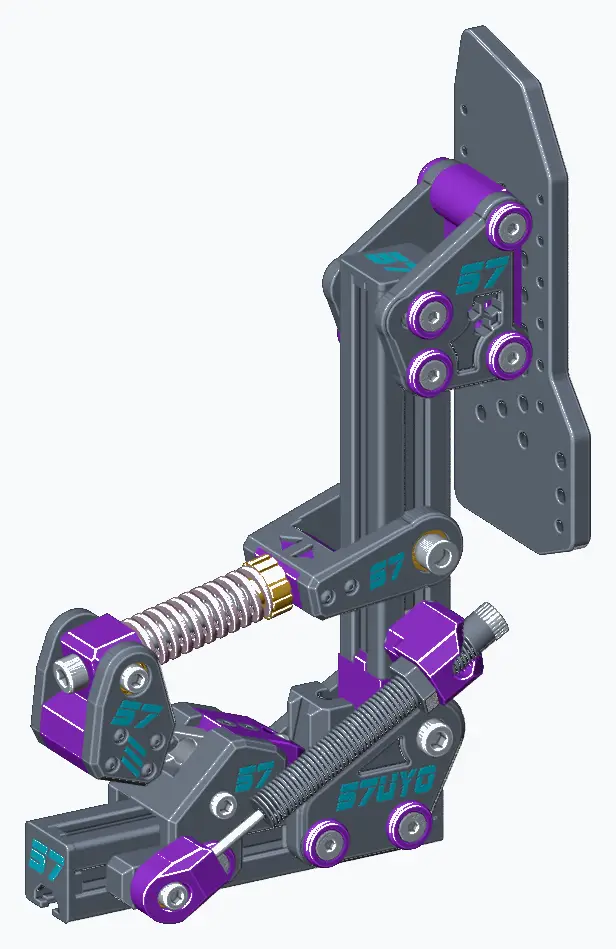
57 Pedals Lite MK-II assembly manual
Assembly guide · 18 Nov 2026
Part of the 57 Pedals Lite MK-II design · parts list
Throttle
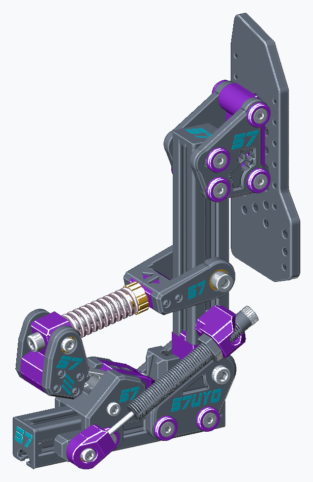
The Lite builds the same way as the 57 Pedals Pro MK-II throttle: follow Steps 1–28. The Lite has no dampers, so the damper steps of the Pro manual (29–35) are left out; the downloadable PDF is the full Pro MK-II guide. Lite parts are the original MK-II designs, so some shapes differ slightly from the pictures. Mechanical assembly only. Controller wiring and pedal-to-rig mounting are separate.
Keep previously fitted parts in place as you move to the next step. Some close-ups omit surrounding parts to expose the joint.
Parts, packs to order and prices: see the parts list.
Before you start
- M8 tap and tap wrench
- Tap one end of each 150 mm profile, minimum 16 mm usable thread depth.
- Hex keys
- Use the correct key for each socket or countersunk head.
- Heat-insert installation tool
- Fit inserts squarely; allow the plastic to cool before inserting screws.
- Temporary bearing press
- Long M8 and M6 bolts, two large washers and matching nuts. These are tools, not extra installed hardware.
- Check the orientation
- Inside washers contact the bearing inner race. Press-fit force goes through the outer ring.
- T-nut types
- M6: spring-loaded roll-in. M8: heavy-duty sliding T-nuts; insert these before closing the profile end.
- Screw lengths
- Socket bolts are measured under the head. Countersunk screws are measured including the head. Use the JDM washer/screw sets as supplied.
Hardware reference
- M8 socket: 16 / 50 / 100 mm
- 3 x 16 mm: bottom pivot and spring-pivot arms. 1 x 50 mm: pedal axle. 1 x 100 mm: spring rod.
- M6 socket: 12 / 16 mm
- 2 x 12 mm: rear spring pivot. 4 x 16 mm: three load-cell block, travel stop.
- M6 countersunk
- JDM washer/screw sets at side plates, face mount and LC covers. Two 20 mm screws secure the pedal face.
- M3 screws
- 16 mm for the LC side plates and front spring block.
- M4 countersunk: 10 mm
- Eight screws secure the two load-cell blocks.
- Heat inserts
- M3: 6 mm long. M6: 7 mm long. M8: 8 mm long.
- Bearings and shims
- 608ZZ: 8 x 22 x 7 mm. 696ZZ: 6 x 15 x 5 mm. Rear spring shims: one 1 mm per side.
Step 01
Prepare the two aluminium profiles
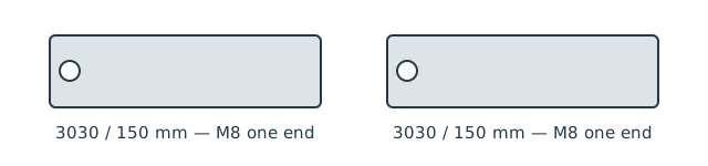
- 2 x 3030 profiles, 150 mm
- M8 tap
- Use two 3030 aluminium profiles, both 150 mm long. Tap the centre hole at ONE end of each profile with M8 thread.
- Minimum usable thread depth: 16 mm. Deburr the ends and remove swarf before assembly.
Step 02
Mount the bottom pivot
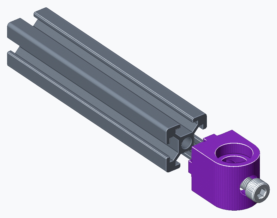
- Bottom pivot
- 1 x M8 x 16 socket bolt
- Fit the locating tabs into the profile slots, with the rounded pivot end facing outward. Secure with one M8 x 16 mm socket bolt. No washer is used here.
Step 03
Fit the main pivot bearings
- 2 x 608ZZ
- Bearing spacer
- Temporary M8 press tools
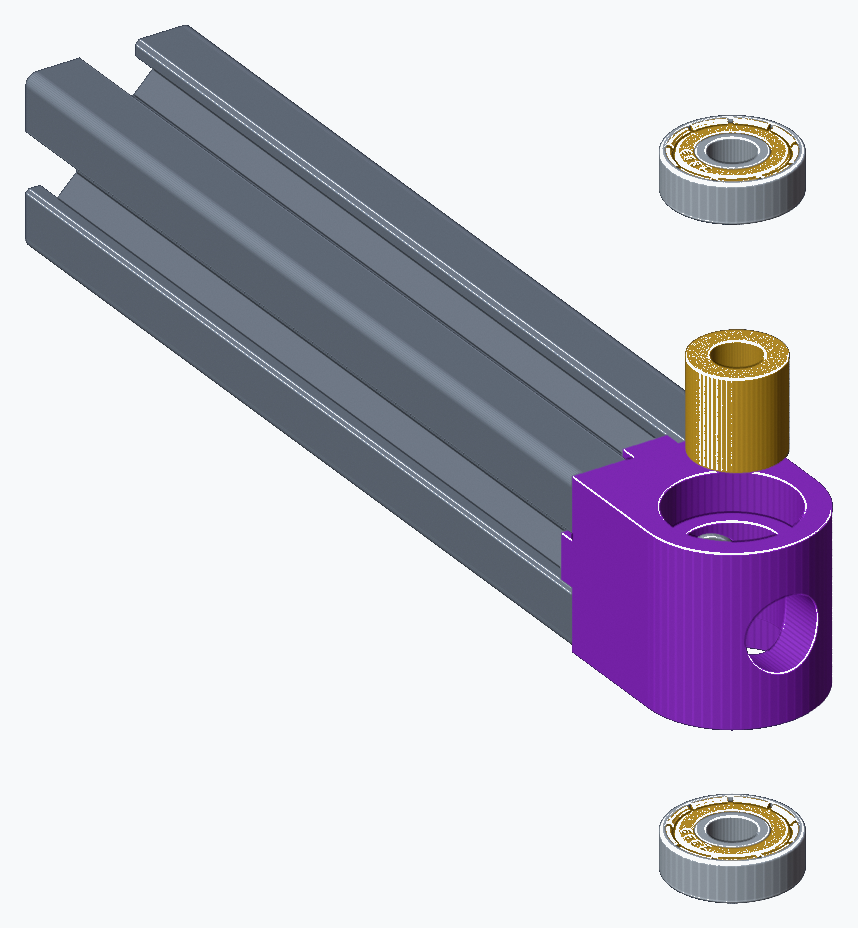
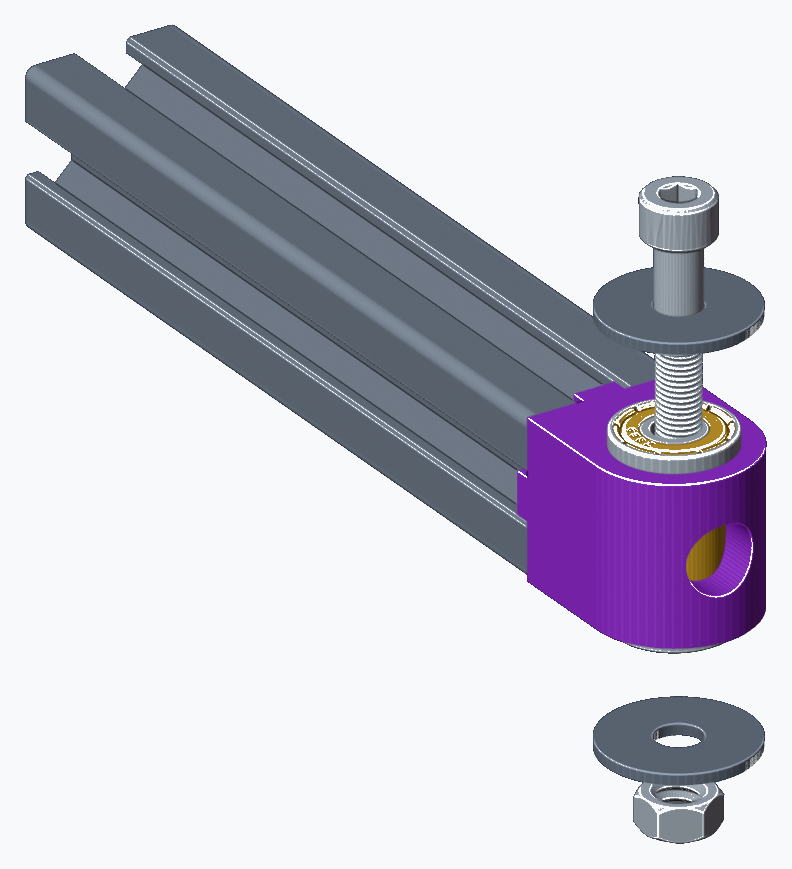
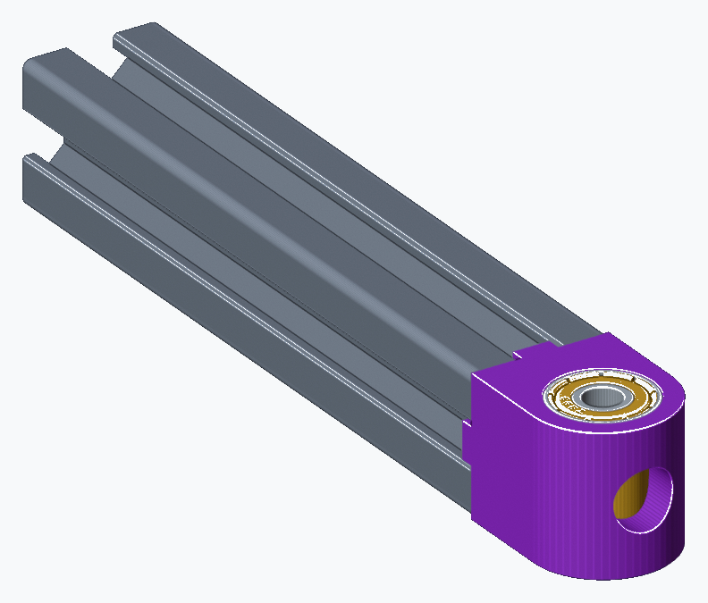
- Fit two 608ZZ bearings with the spacer between their inner races.
- Temporary press: a sufficiently threaded M8 bolt, two large washers and an M8 nut. Apply pressure evenly through the bearing outer rings. Remove the tool after pressing.
Step 04
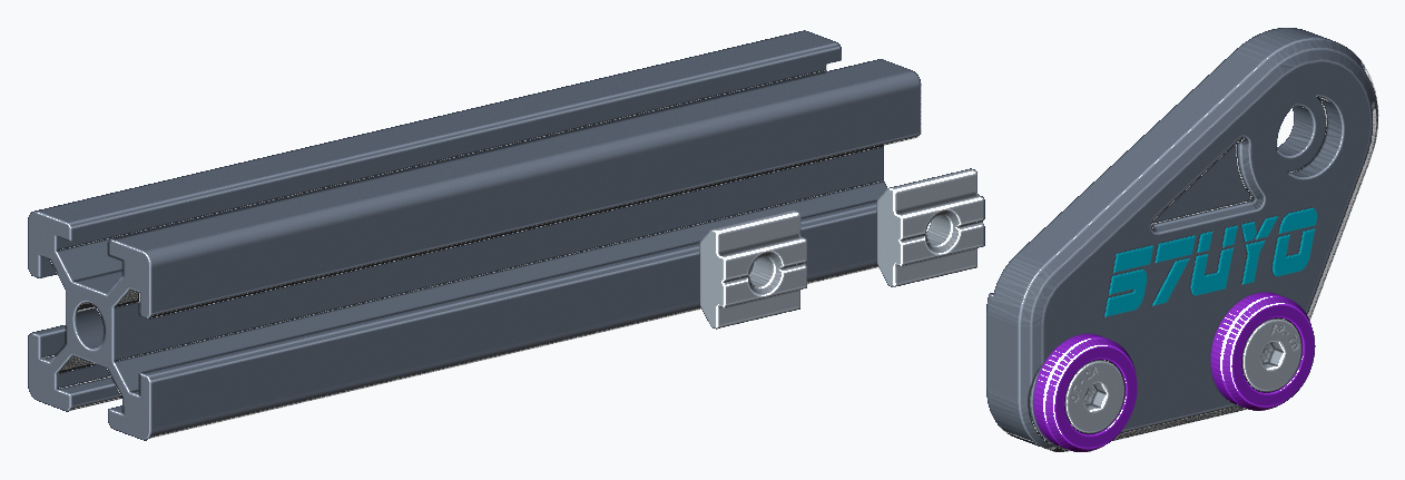
Fit the first base side plate
- First side plate
- 2 x M6 roll-in T-nuts
- 2 x JDM M6 washer/screw sets
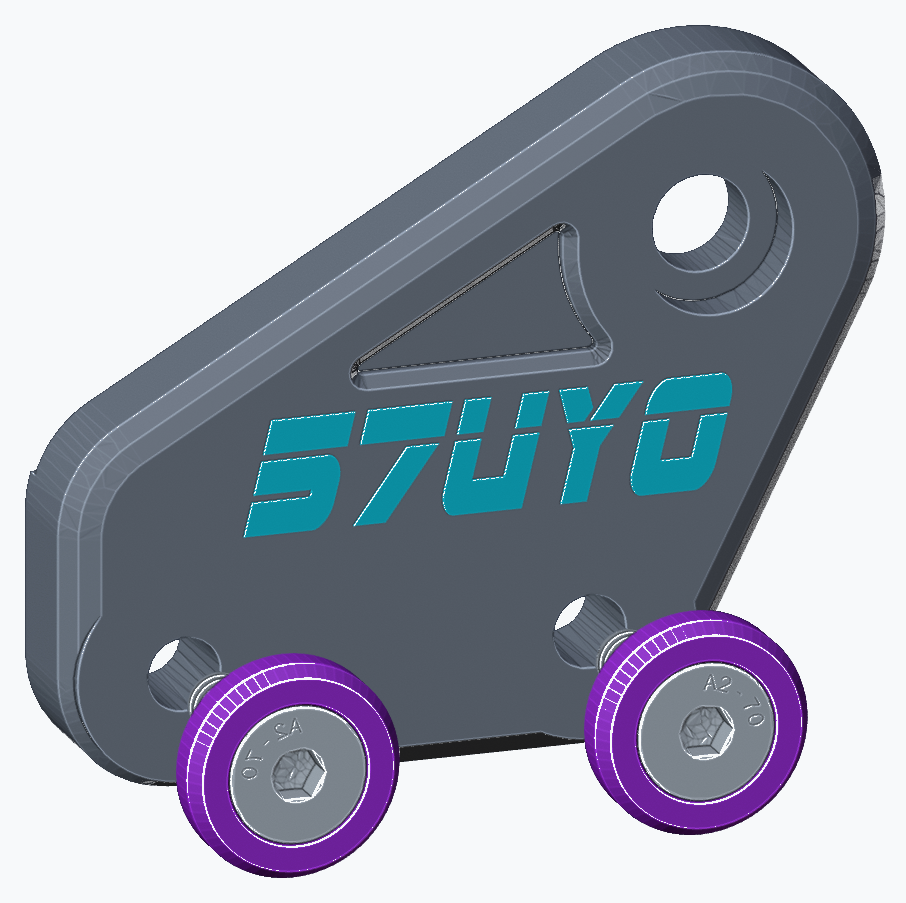
- Fit two spring-loaded M6 roll-in T-nuts in the lower profile. Orient their threaded holes toward the plate.
- Keep the plate upright in its final orientation and secure it with two JDM M6 washer/screw sets.
Step 05
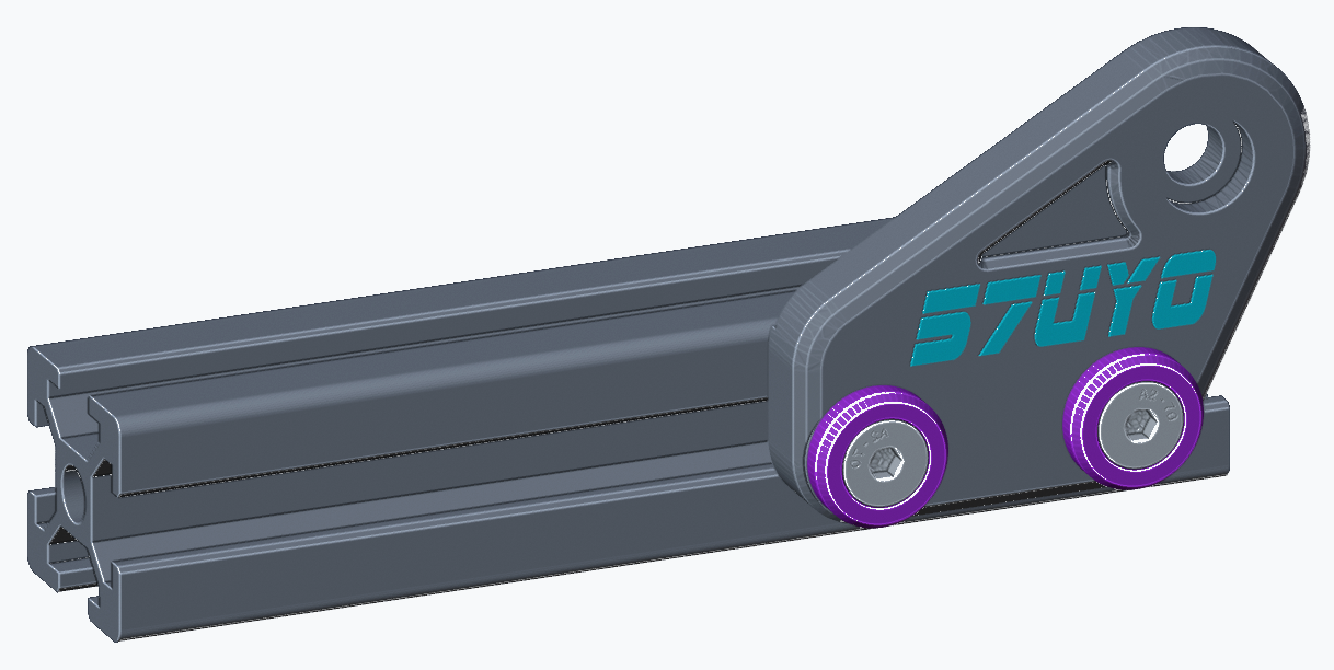
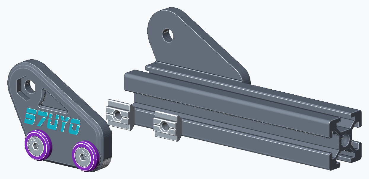
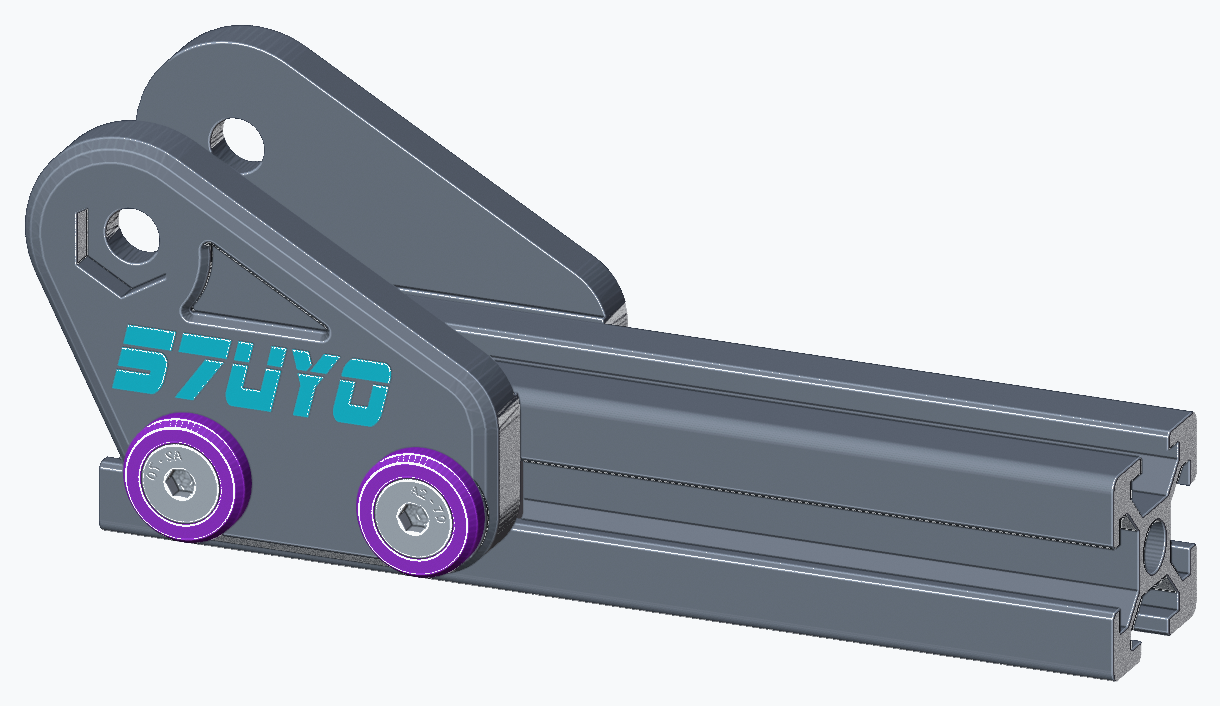
Fit the opposite base side plate
- Opposite side plate
- 2 x M6 roll-in T-nuts
- 2 x JDM M6 washer/screw sets
- Rotate the assembly to access the other side. Fit the second plate with two more M6 roll-in T-nuts and two JDM M6 washer/screw sets.
Step 06
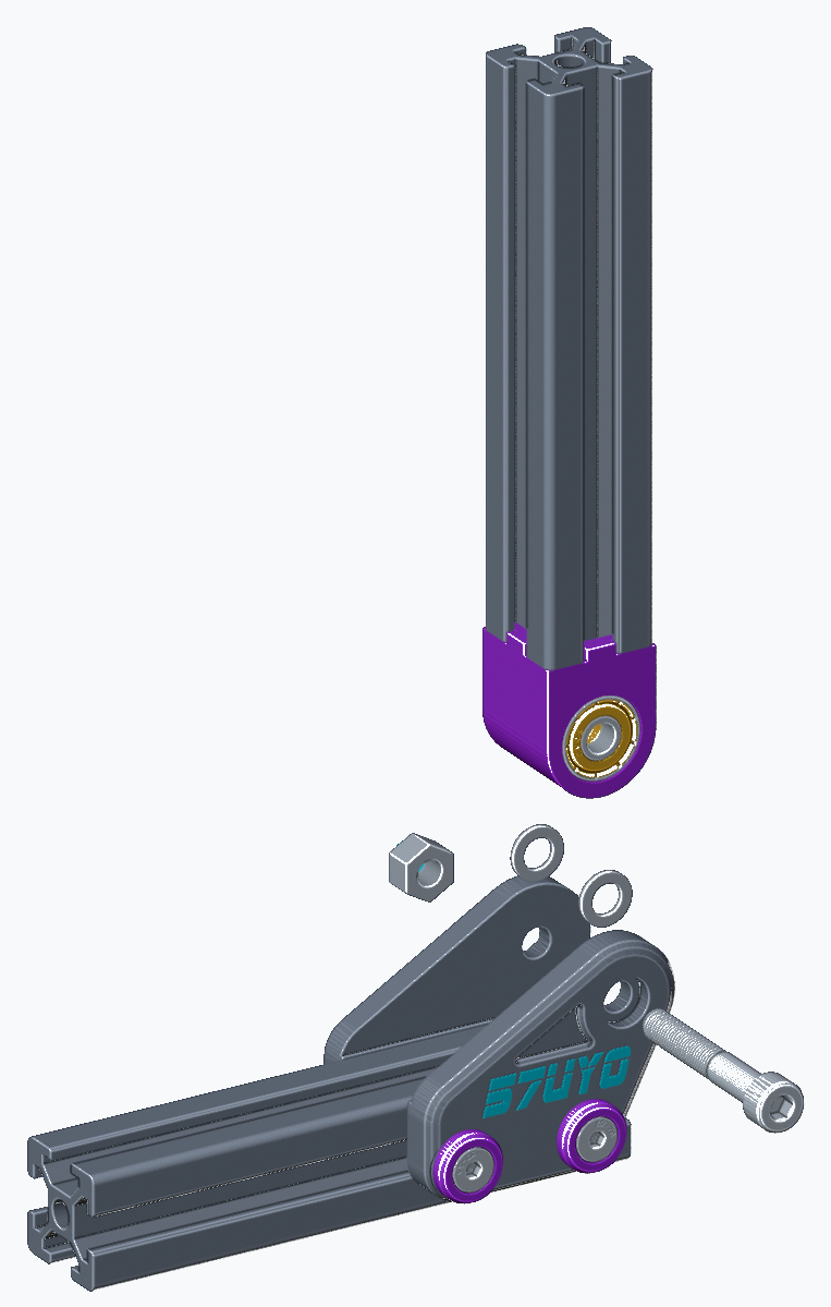
Install the pedal arm
- Pedal arm
- M8 x 50 socket bolt
- 2 x M8 washers
- M8 locknut
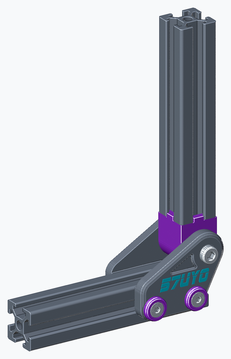
- Axle order: M8 x 50 socket bolt > side plate > M8 washer > arm bearing assembly > M8 washer > opposite side plate > M8 locknut.
- Both washers sit INSIDE the side plates. Tighten securely and check that the arm moves freely.
Step 07
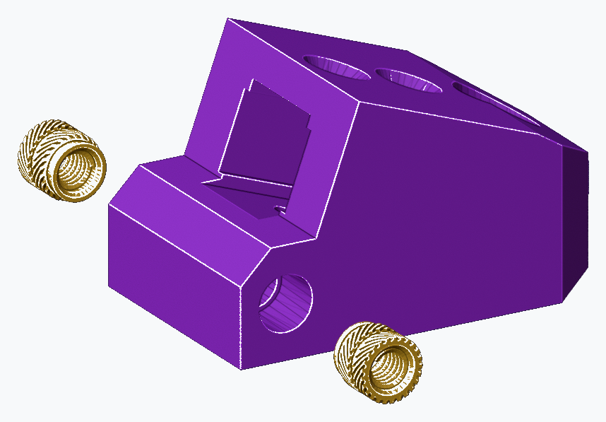
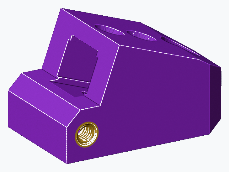
Fit the M6 brass heat-set inserts
- 2 x M6 heat inserts, 7 mm long
- Heat-set one M6 insert into each side of the front load-cell block. Keep them square and allow the block to cool.
Step 08
Assemble the load-cell front block
- Load cell
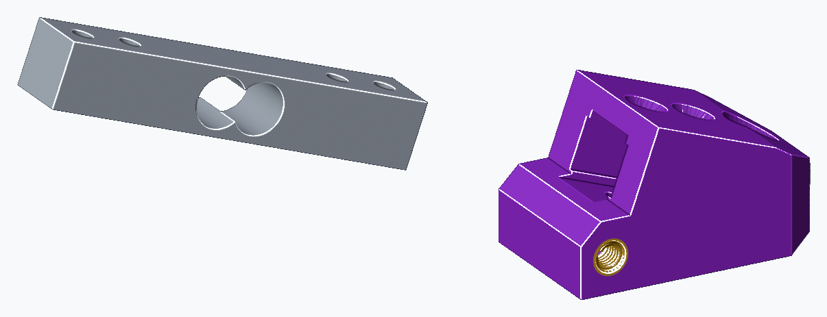
- Front block
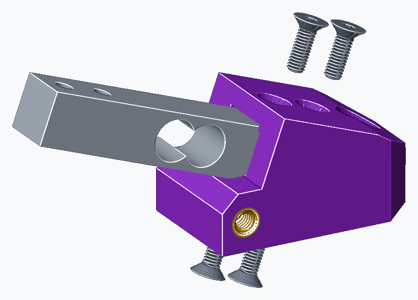
- 4 x M4 x 10 countersunk screws
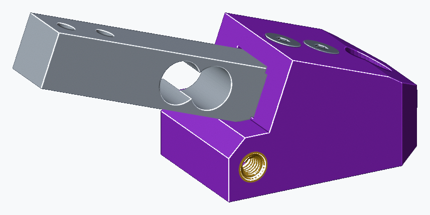
- Slide the load cell into the prepared front block. Secure with four M4 x 10 mm countersunk screws: two from above and two from below.
Step 09
Prepare the rear load-cell block
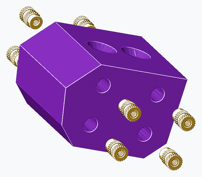
- 8 x M3 heat inserts, 6 mm long
- Fit four M3 x 6 mm heat inserts into EACH side of the rear load-cell block: eight total. Allow to cool.
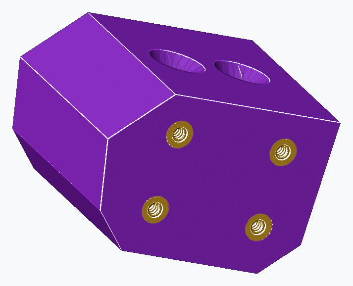
Step 10
Fit the rear block to the load cell
- Rear LC block
- 4 x M4 x 10 countersunk screws
- Slide the rear block onto the opposite end of the load cell, with its eight M3 inserts already fitted. Secure with four M4 x 10 mm countersunk screws.
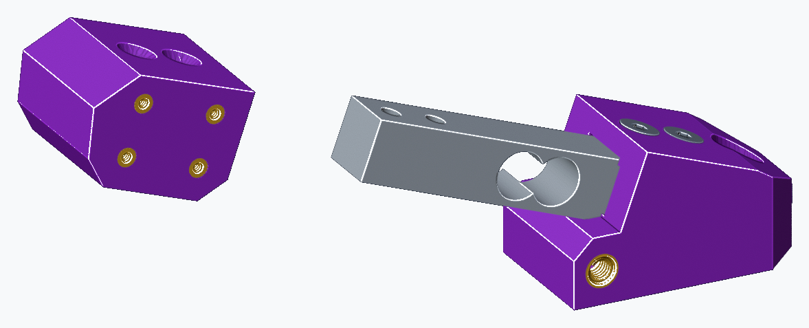
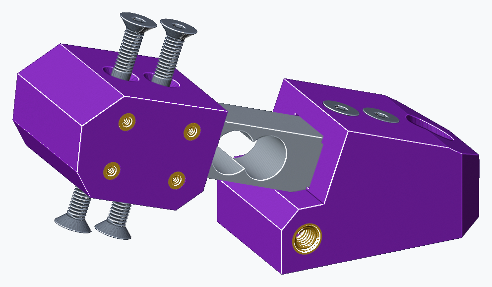
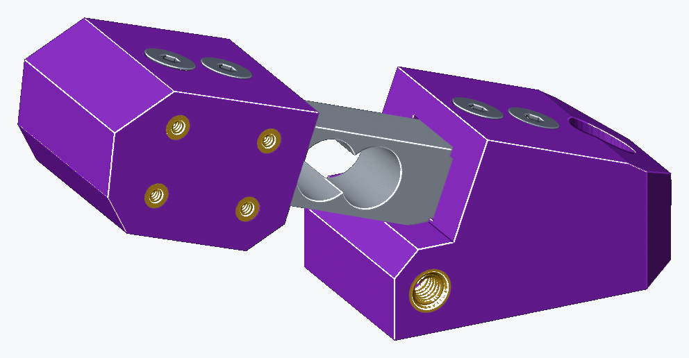
Step 11
Fit the load-cell side-plate bearings
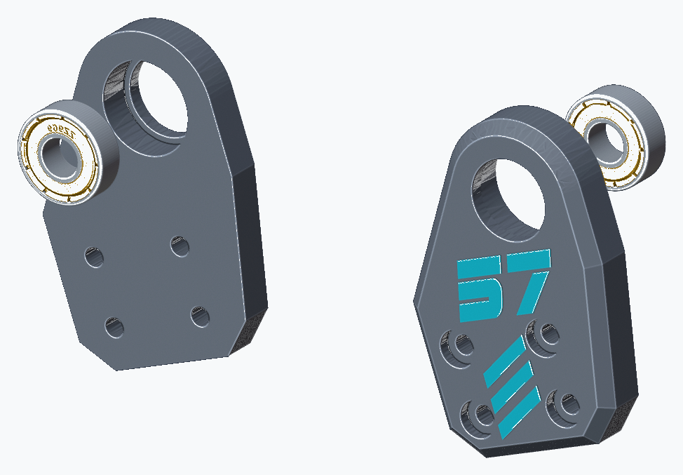
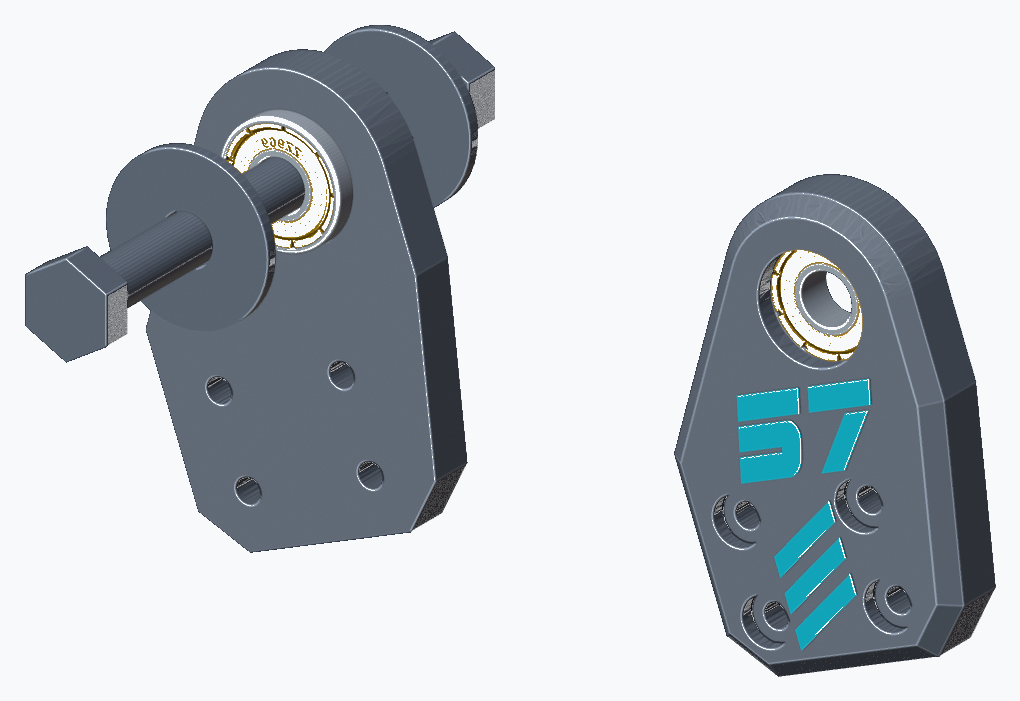
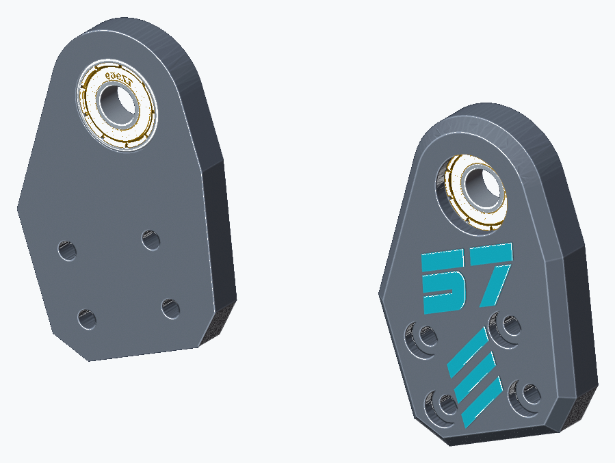
- 2 x 696ZZ bearings
- Temporary M6 press tools
- Press both 696ZZ bearings into the inner faces of the load-cell side plates until FLUSH. The illustrated plates are mirrored, with one logo face shown.
- Use a longer M6 bolt, two large washers and an M6 nut as a temporary press. Press squarely on the bearing outer ring, then remove the tools.
Step 12
Mount the load-cell side plates
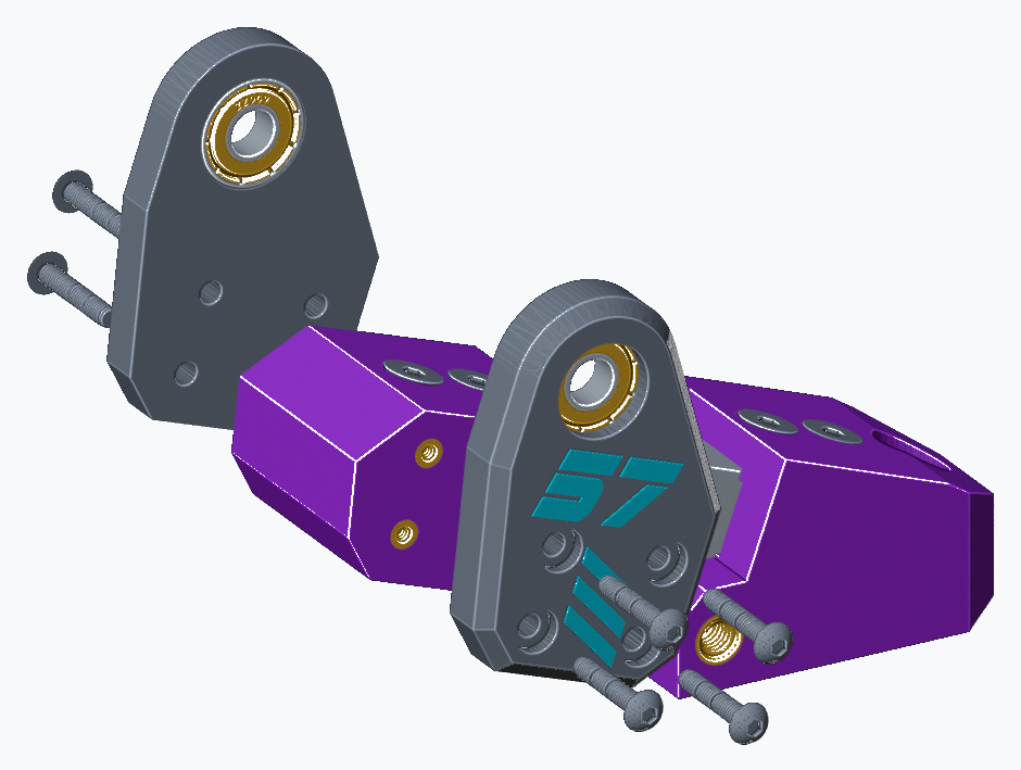
- 2 prepared LC side plates
- 8 x M3 x 16 screws
- Mount both prepared plates to the rear load-cell block with four M3 x 16 mm screws per side. Logos face outward.
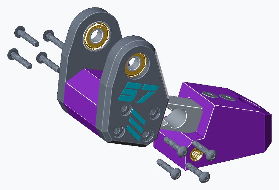
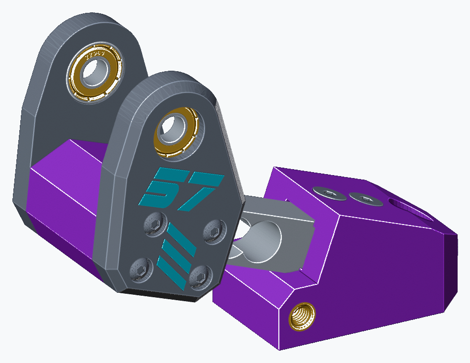
Step 13
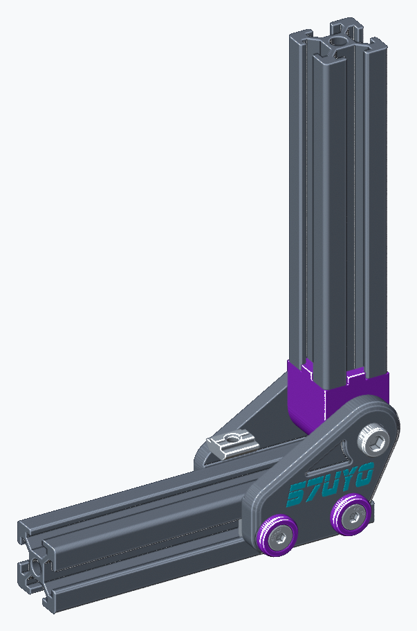
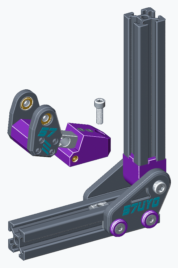
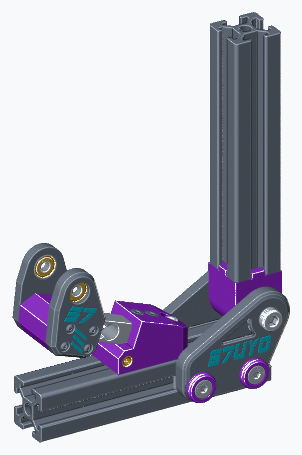
Mount the load-cell assembly on the base profile
- 1 x M6 x 16 socket bolt
- 1 x M6 roll-in T-nut
- Fit an M6 spring-loaded roll-in T-nut in the top slot of the base profile, threaded hole upward. Mount the front load-cell block with one M6 x 16 mm socket bolt.
Step 14
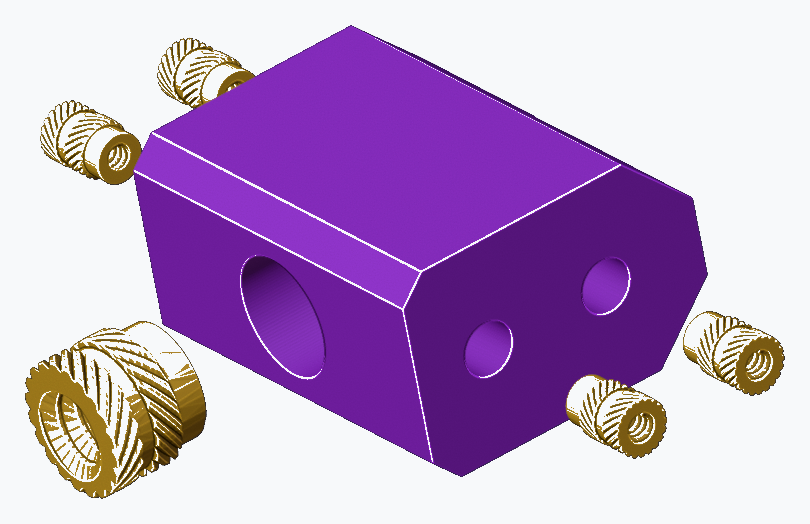
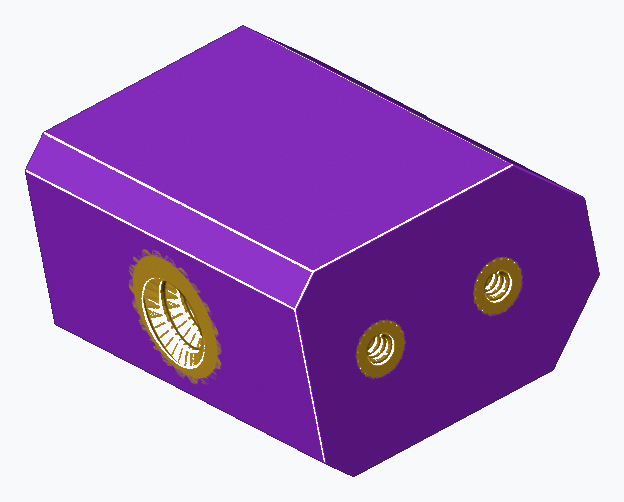
Prepare the front spring block
- 4 x M3 x 6 heat inserts
- 1 x M8 heat insert, 8 mm long
- Fit four M3 x 6 mm heat inserts, two per side of the front spring block. Fit the M8 x 8 mm insert from the front. Allow to cool.
Step 15
Fit the spring-pivot arm bearings
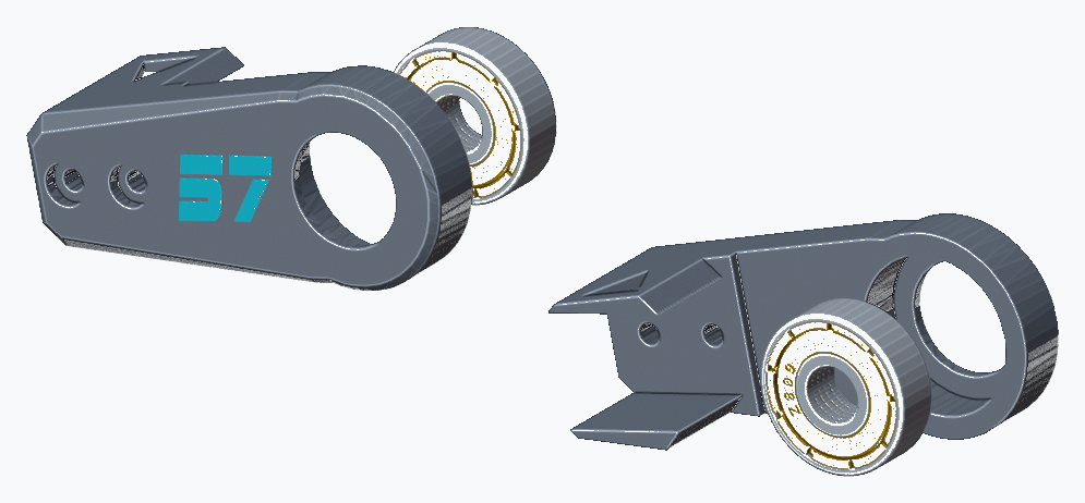
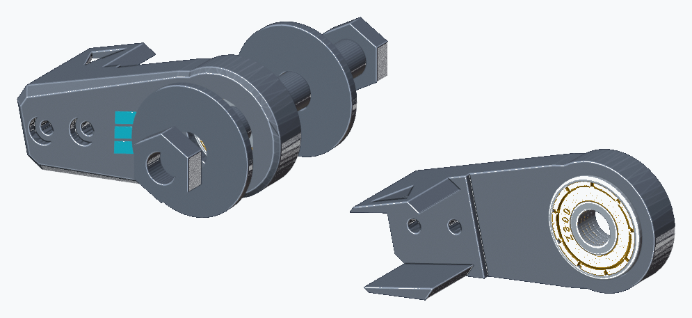
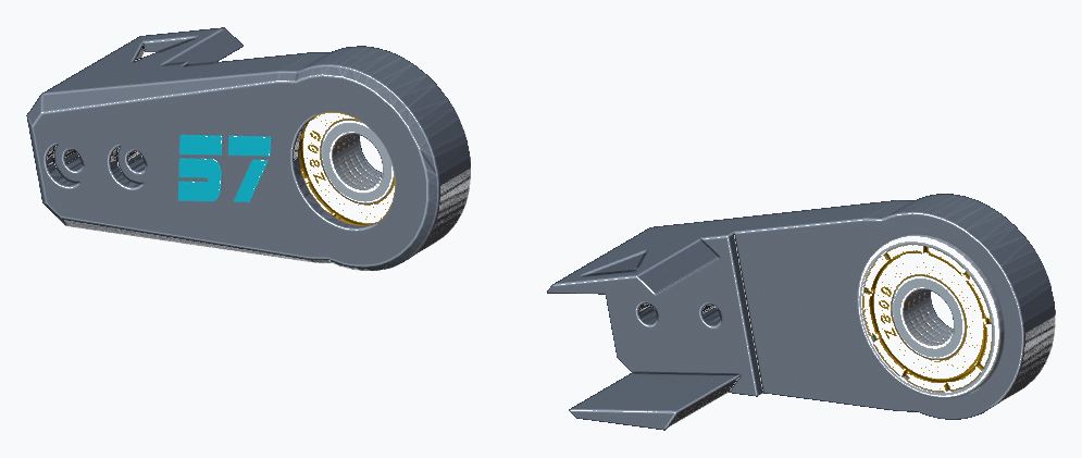
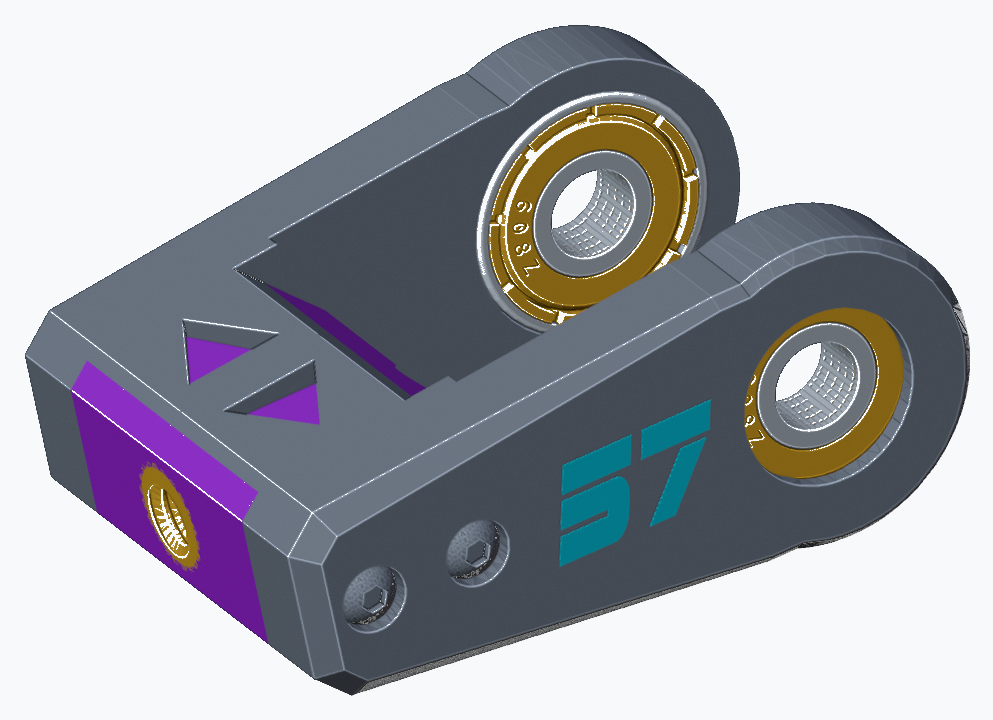
Step 16
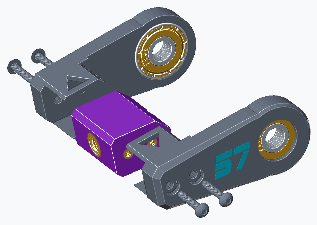
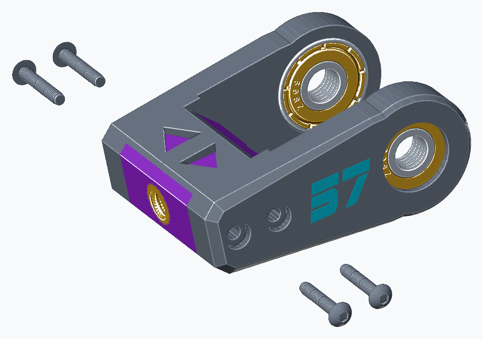
Mount the front spring block between the pivot arms
- Front spring block
- 2 pivot arms
- 4 x M3 x 16 screws
- Mount the front spring block between the prepared pivot arms using four M3 x 16 mm screws, two per side. Keep the arms facing right as shown.
Step 17
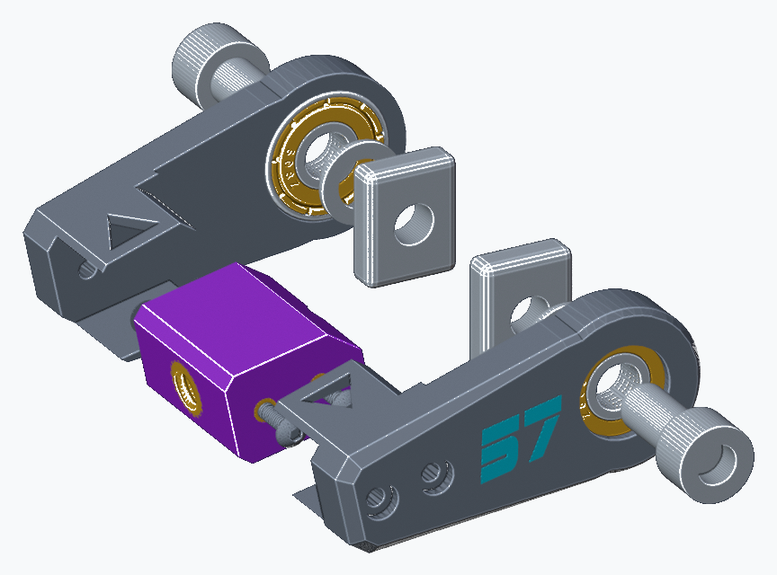
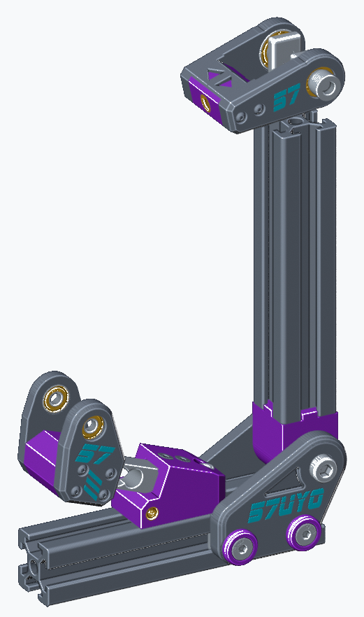
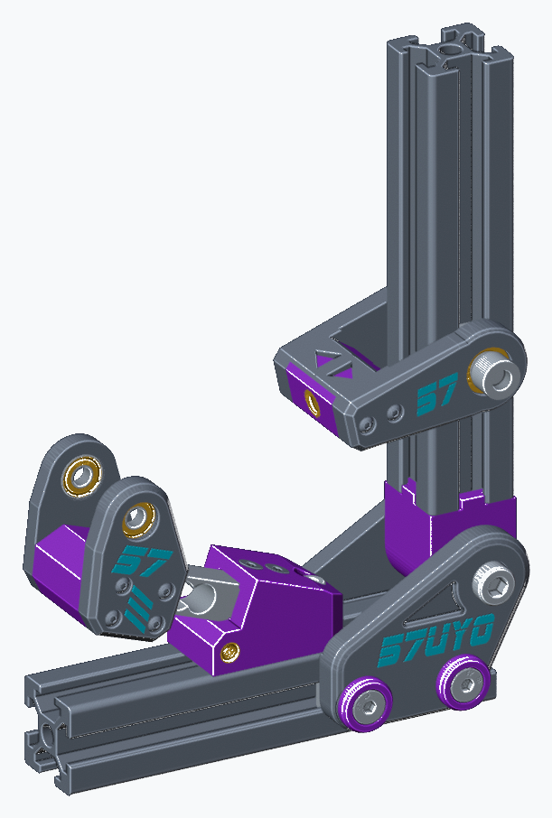
Slide the spring pivot onto the pedal arm
- 2 x M8 x 16 socket bolts
- 2 x M8 washers
- 2 x heavy-duty M8 T-nuts
- Fit one M8 x 16 socket bolt from outside each bearing. Place one M8 washer on the INSIDE, between the bearing inner race and profile.
- Half-thread each HEAVY-DUTY M8 T-nut onto its bolt. Slide both T-nuts into the arm slots from the open end, position the pivot, then tighten.
Step 18
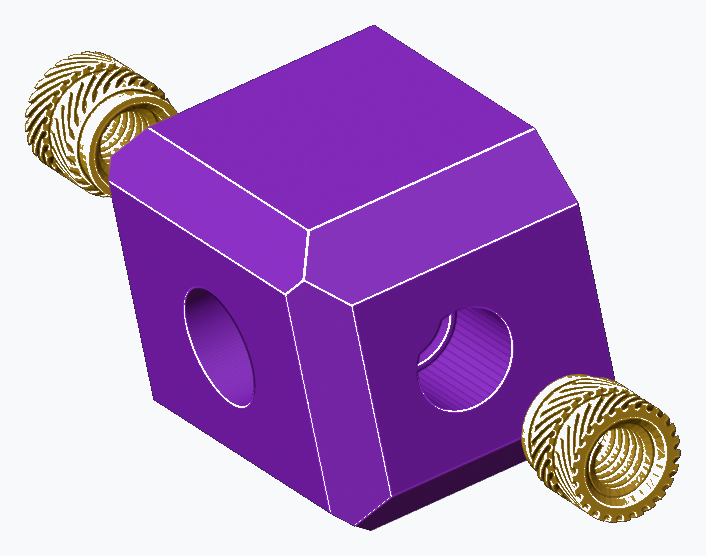
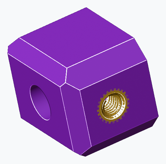
Prepare the rear spring block
- 2 x M6 heat inserts, 7 mm long
- Fit one M6 insert into each side of the rear spring block. Allow to cool.
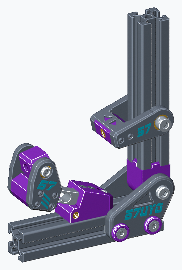
Step 19
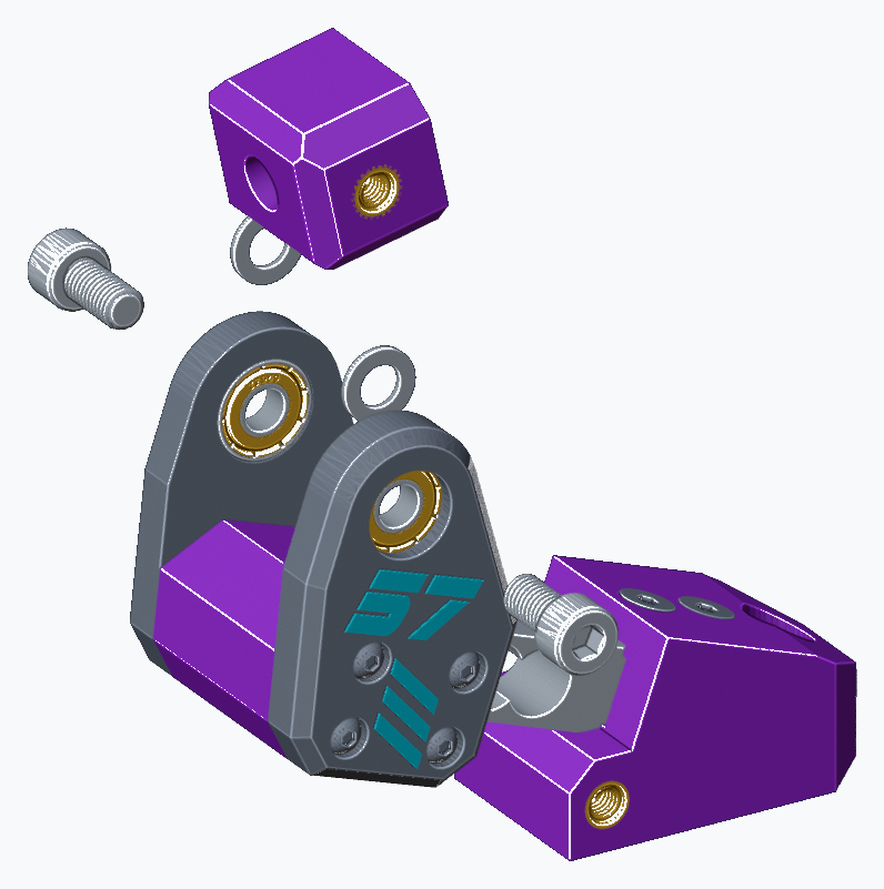
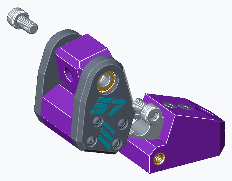
Mount the rear spring block between the load-cell uprights
- 2 x M6 x 12 socket bolts
- 2 x M6 shims, 1 mm thick
- Position the rear spring block between the load-cell uprights. Fit ONE 1 mm M6 shim on each side, contacting the bearing inner race.
- Secure from outside with two M6 x 12 mm socket bolts. A 1.2 mm washer per side is the agreed fallback if 1 mm shims are unavailable. Check free movement.
Step 20
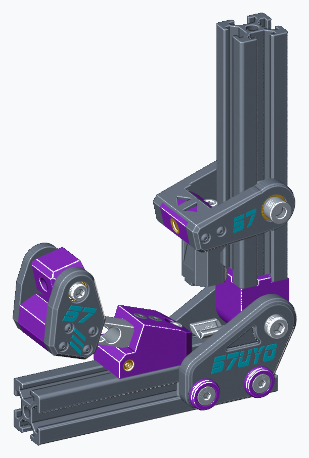
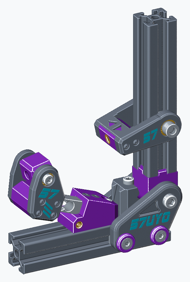
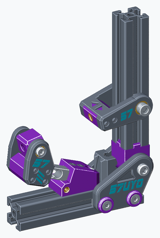
Mount the pedal travel stop
- Travel stop
- 1 x M6 roll-in T-nut
- 1 x M6 x 16 socket bolt
- Fit the M6 roll-in T-nut into the base profile. Place the travel stop over it and secure with an M6 x 16 mm socket bolt. The stop sits under the spring.
Step 21
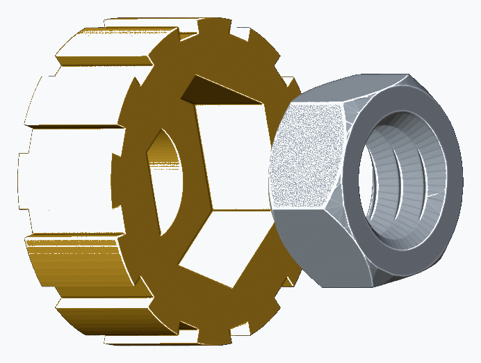
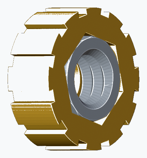
Prepare the spring compression ring
- Compression ring
- 1 x M8 locknut
- Press-fit the M8 locknut fully into the compression ring hex pocket. The ring will sit in front of the spring.
Step 22
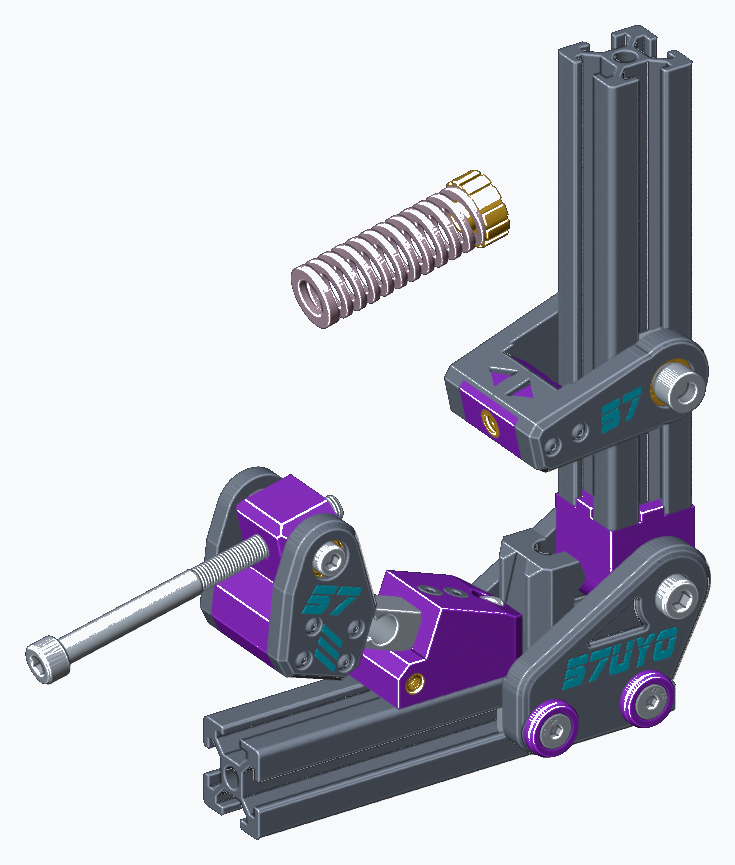
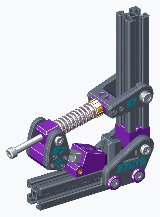
Install the spring and M8 x 100 mm bolt
- Spring
- Prepared compression ring
- 1 x M8 x 100 socket bolt
- Insert the M8 x 100 mm bolt from behind the rear spring block. Place the spring and prepared compression ring between the blocks, with the ring in front of the spring.
- Advance the bolt and screw the assembly together. The travel stop is already fitted under the spring.
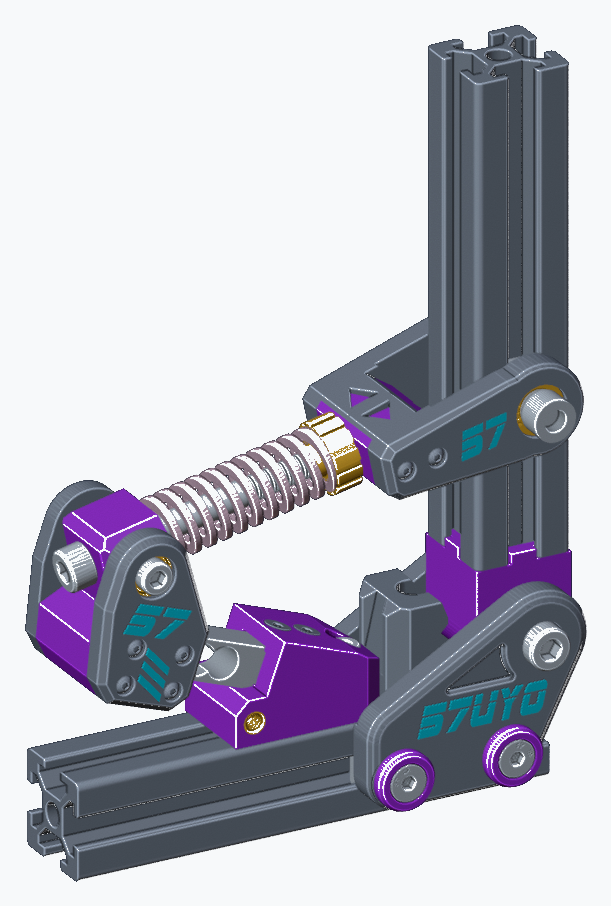
Step 23
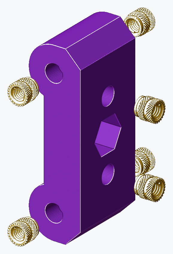
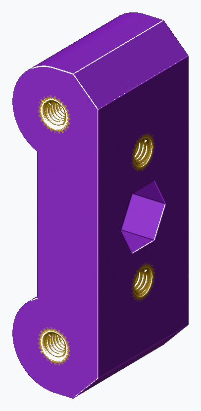
Prepare the pedal-face mounting block
- Pedal-face mount block
- 6 x M6 heat inserts, 7 mm long
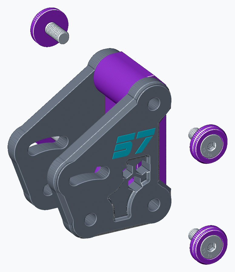
- Fit six M6 inserts: two in each side face and two from the back for the pedal-face screws. Allow to cool.
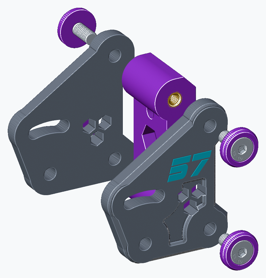
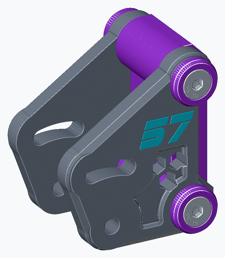
Step 24
Fit the pedal-face mounting side plates
- Mount block
- 2 side plates
- 4 x JDM M6 washer/screw sets
- Fit the two side plates to the prepared mounting block with two JDM M6 washers and countersunk screws per side. Leave the two rear inserts available for the pedal face.
Step 25
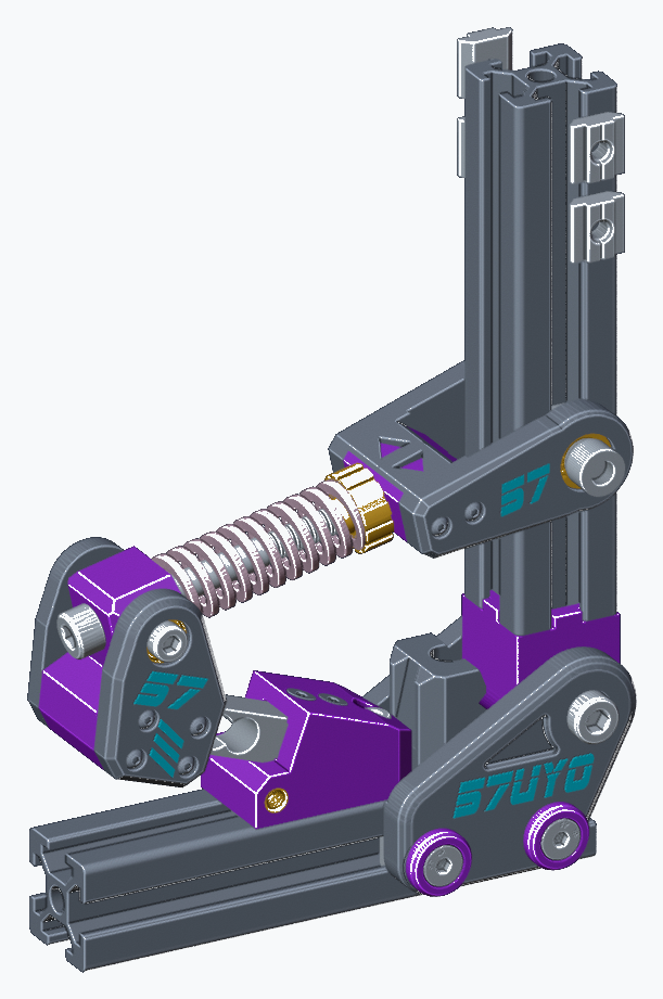
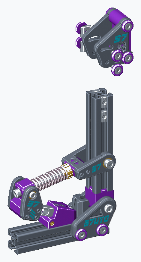
Fit the pedal-face mount onto the pedal arm
- 4 x M6 roll-in T-nuts
- 4 x JDM M6 washer/screw sets
- Fit two M6 roll-in T-nuts into EACH side of the pedal arm. Slide the prepared pedal-face mount onto the arm. Align and secure with four additional JDM M6 washer/screw sets.
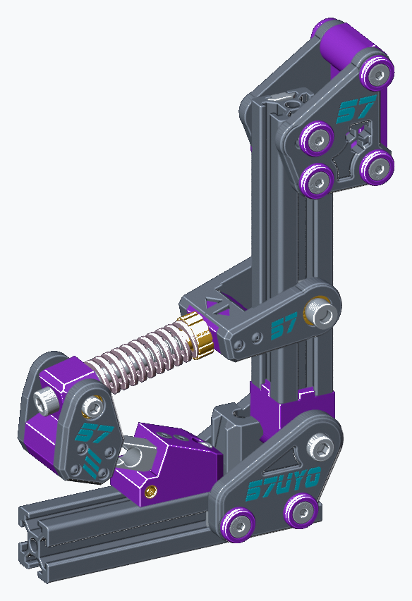
Step 26
Fit the load-cell cover plates
- 2 LC covers
- 2 x M6 roll-in T-nuts
- 2 washer/screw sets
- 2 x M6 x 16 socket bolts
- Each cover uses a washer and M6 countersunk screw into a roll-in T-nut INSIDE the profile, plus an M6 x 16 mm socket bolt into the load-cell block.
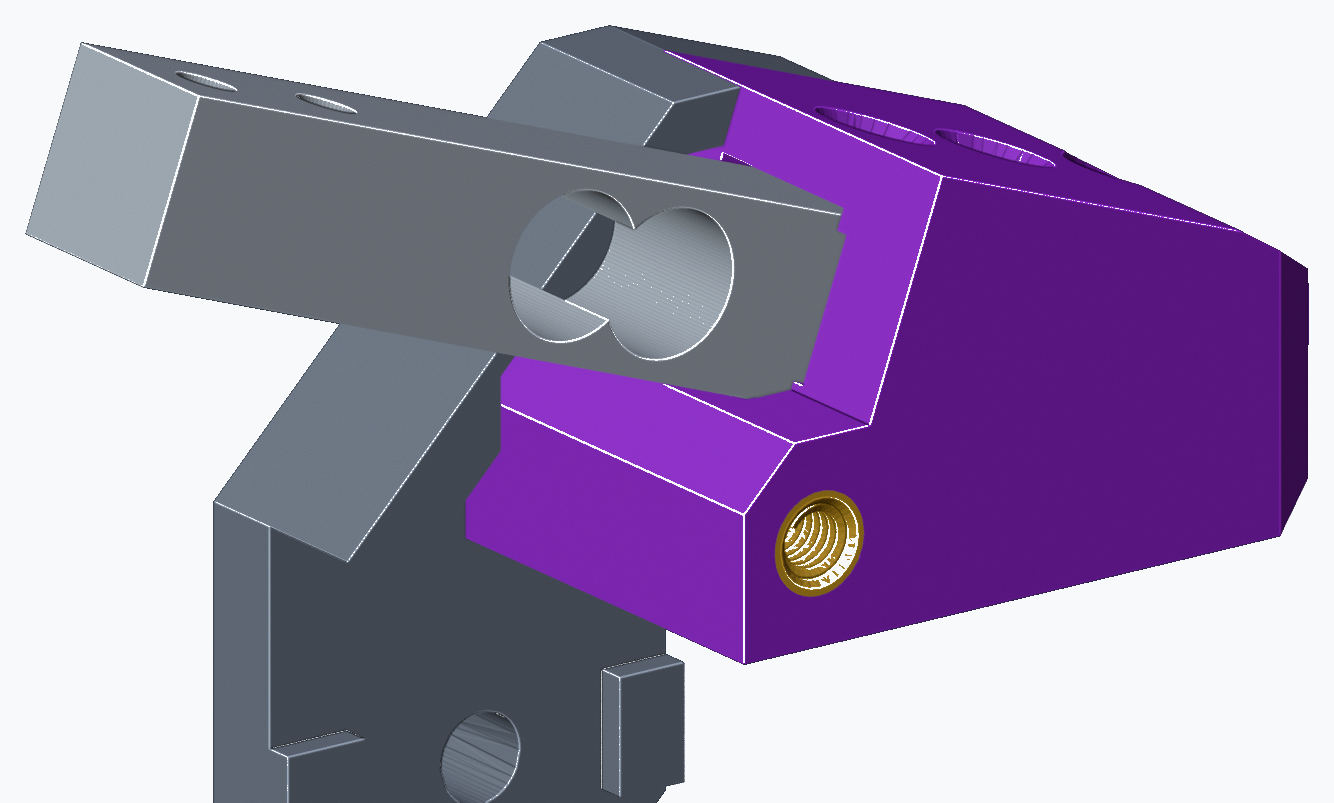
- Route the load-cell cable through the gap between the BACK EDGE of the block and the covering protrusion on the smaller, far-side plate. The close-up shows the inner side.
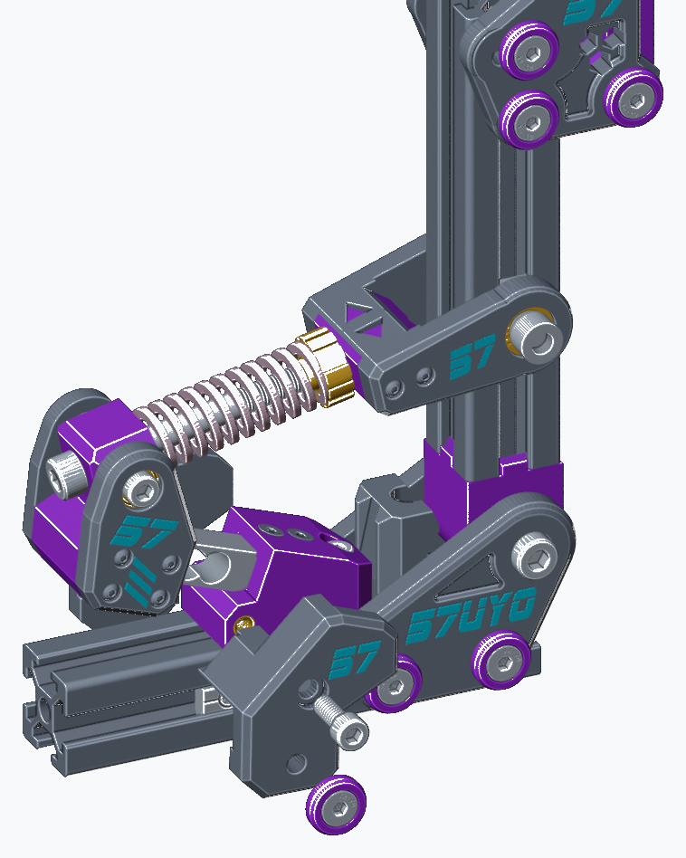
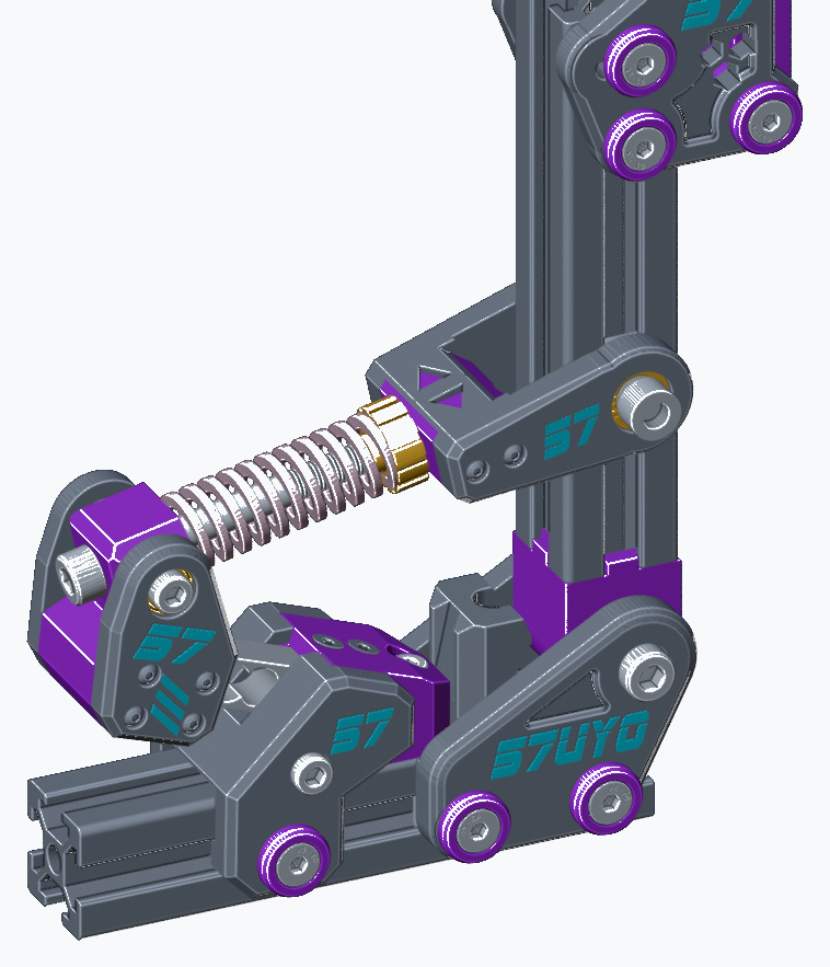
Step 27
Fit the profile-end covers
- 3 profile covers
- Optional hot glue
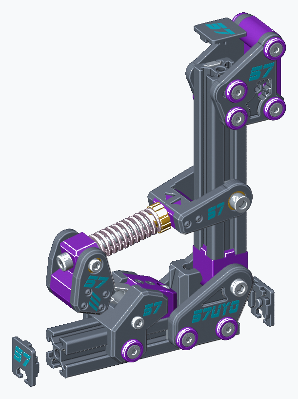
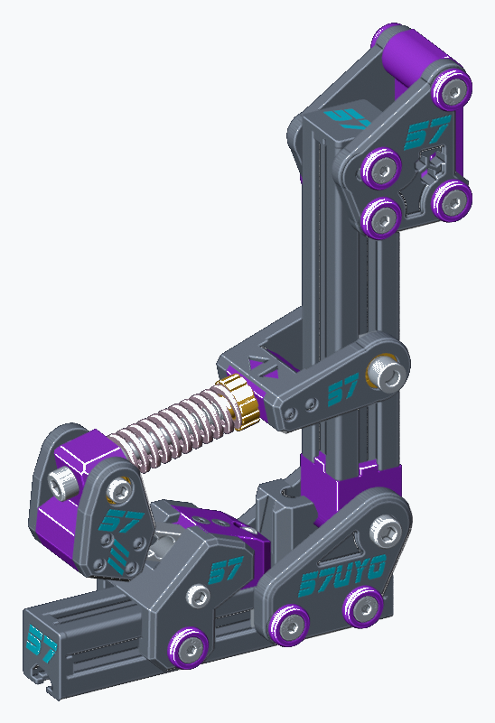
- Press the two covers WITH T-nut cutouts into the ends of the base profile. Fit the solid cover WITHOUT a cutout or logo at the top of the pedal arm.
- If needed, use a small dab of hot glue to hold the covers in place.
Step 28
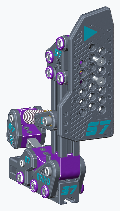
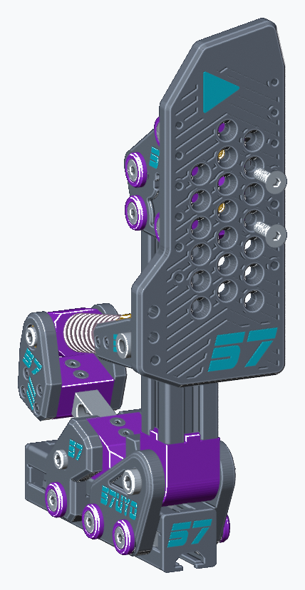
Mount the pedal face
- Pedal face
- 2 x M6 x 20 countersunk screws
- Rotate the pedal to the front. Mount the pedal face to its block with two M6 x 20 mm countersunk screws, then tighten evenly.
More guides
Assembly guide · 16 Nov 2026
57 DIY Pro Pedals MK-II: assembly manual
Illustrated step-by-step assembly of the 57 DIY Pro Pedals MK-II: throttle, with the parts for every step and a PDF to download.
How-to · 6 Nov 2025
Universal LC Pedal Controller - Simagic P2000 Control Box
DIY Load Cell pedals are great, but there is one big problem - the controller! Never fear - Simagic is here! A lot of us already bought the Simagic P2000 Haptic Control Box to driv

How-to · 28 Apr 2023
Fanashifter Sequential Interface
In this article we are exploring a very simple interface for any sequential shifter based on two switches to connect directly to a Fanatec Wheelbase. You can use it for Sequential,